Introduction to Factor of Safety
Recently, a person emailed me (kartbuilding[at]gmail.com) asking about the “factor of safety” (FoS) required when undertaking calculations to design and make a go-kart. The “factor of safety” is the maximum force and stress a kart can possibly undergo, multiplied by a suitable factor/multiplier. Ideally if the maximum force and stress a kart can endure is calculated, then this factor gets multiplied by the factor of safety.
Having a FoS of 1, means that a Go-Kart is not “overengineered”, and nothing extraordinary will occur. It is when the “extraordinary” or unthinkable happens, that the FoS comes into effect.
Quantifying the Factor of Safety
Quantifying the FoS for a Go-Kart is not an easy task! It certainly cannot be applied to the entire Go-Kart, but parts of it, e.g. the chassis, transmission, brakes, etc. The same FoS cannot be applied to the chassis in every Go-Kart. The purpose and category of Go-Kart must be firstly determined. I.E. is it a racing kart and in what category of racing kart? Once the category and type of Go-Kart is determined, then a FoS can be obtained.
NatSKA – Classes of Racing Karts, and Safety Regulations
![]() NatSKA (The National Association for School and Youth Group Karting) governs the sport and activity of karting in schools throughout the United Kingdom. The association holds race meetings run under strict regulations of its governing body (Motor Sports Association), and periodically publishes a Handbook and Regulations. The most recent Handbook and Regulations (2007) outlines the various “classes” of karts, and range from Class 1 (50cc Single Ratio Open) to Class 16 (Honda C70, C90 and C90 Cub Gearbox). Specific specifications (including safety) are outlined for areas of the kart. The following is an edited exerpt from the NatSKA Kart Regulations on chassis design:
NatSKA (The National Association for School and Youth Group Karting) governs the sport and activity of karting in schools throughout the United Kingdom. The association holds race meetings run under strict regulations of its governing body (Motor Sports Association), and periodically publishes a Handbook and Regulations. The most recent Handbook and Regulations (2007) outlines the various “classes” of karts, and range from Class 1 (50cc Single Ratio Open) to Class 16 (Honda C70, C90 and C90 Cub Gearbox). Specific specifications (including safety) are outlined for areas of the kart. The following is an edited exerpt from the NatSKA Kart Regulations on chassis design:
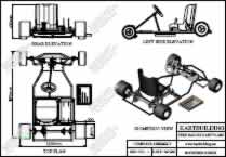
The chassis in general shall be of safe, sound and adequately strong construction and shall not include any components of a temporary nature. Specifically, the wheel base is to be a minimum of 101cm and maximum of 127cm. The maximum length of the kart, including bodywork shall not exceed 210cm. No kart is to weigh more than 100kg without the driver.
I highly recommend that the NatSKA handbook and regulations are read and followed, especially if other people are driving and racing your Go-Kart. At the very least, excellent safety guidelines are outlined.
More Technical “Factor of Safety” etc. – Formula Racing
 If you are designing your own Kart on a CAD system etc. some software will allow you to carry out “Stress Analysis” of components. Some examples of CAD software packages are: Solidworks and Cosmos, Pro-Engineer and Pro-Mechanica. These software packages will allow you to carry out simulation of kart components, allowing you to place particular loads throughout, and calculate a FoS automatically! If you are heavily involved in design and analysis of karts, this CAD software will speed things up, and provide a wealth of information.
Stress Test and Factor of Safety Analysis of a Front Stub Axle from a Go-Kart
 As an example of the amount of information and the ease at which CAD software can calculate the FOS, a stress test was carried out on a Front Stub Axle from a Go-Kart, as can be seen in the image on the left. The entire CAD HTML Stress Analysis is also available. The plans for this “Front Stub Axle” are contained in the Complete Set of Racing Kart Plans.
This test, taking a total of 10 minutes to model and analyse, found that, if a loading of 50 kilograms were placed onto the steering arm, that the resulting Factor of Safety would be 1.466. Therefore, this Front Stub axle is slightly overdesigned. An in-depth knowledge of the individual forces involved in a Go-Kart would be required for an entire Stress Analysis.
Factors of Safety for Go-Karts in Amusements and Funparks
In doing some research on Factor of Safety for Go-Karts, I came across an “Amusements Devices Act” which makes specific references to Go-Karts and the required Factor of Safety! Although the act (legally binding), has been superseded by a later document, the numbers and references are interesting to see. Part IV of the above act, pertains specifically to Kart Design! An excerpt of its legal requirements are:
- The speed of an adult kart shall be limited or governed so as not to exceed 45 kilometres per hour. R.R.O. 1990, Reg. 20, s. 40 (2).
- The seat, back rest and leg area of every kart shall be so designed as to retain the driver inside the kart in the event of a collision at the front, rear or side of the kart. R.R.O. 1990, Reg. 20, s. 41.
- Rotating, moving or hot engine parts of a kart that may constitute a hazard to an occupant of the kart shall be shielded to prevent burns to the occupant or the entanglement of the occupant’s hair, hands or clothing. R.R.O. 1990, Reg. 20, s. 42.
- The wheels of a kart shall be so enclosed or guarded that the wheel of one kart cannot interlock with or ride over the wheels of another kart.
Factor of Safety on Formula Racing Cars
Various universities are taking part in “Formula Student” lots of readily available information about building advanced racing Cars is available. Two excellent reports on designing formula racing cars can be found here and here. The latter document has a section on “Factor of Safety Development”.
Conclusion to Factor of Safety when Designing Karts
The materials used, and the forces involved make the calculations for FOS quite difficult. CAD software makes things much easier, allowing you to select the materials from a drop-down menu, and allowing you to apply forces wherever you require. CAD software will also allow you to change material thicknesses to achieve an optimum FOS, and weight balance.
Using your common sense, and reinforcing areas which would potentially fail in a collision will go a long way in having a robust Go-Kart.
If you have any queries or questions, drop me an email or leave a comment below.
 The
The 

 The Center Shaft with its Friction shoes is placed onto the engine next. There should be a “keyway” cut into the inner diameter of the clutch shaft which should align with a keyway in the engine’s shaft. This keyway makes sure that the “Center Shaft” will rotate with the engine. To stop the “Center Shaft” from slipping out off the engine shaft, there is a hole to allow a “grubscrew”. A grubscrew is where a threaded small bolt will screw through the Center shaft and tighten in on the engine shaft. You may or may not receive the rectangular metal “key” with the centrifugal clutch or not. I suggest you visit a lawnmower repair shop or a hardware store to obtain a suitable “key”. Below is a photo of the Centrifugal clutch transmission complete. A plastic chain guard can also be seen. If your engine does not have a keyway, and perhaps has another PTO (power take off)
 On Centrifugal Clutches, the small sprocket attached to the “Bell Housing” has typically 10 teeth (although this can vary). As a rough estimate, a gear ratio of 5:1 is needed for a standard/typical go-kart/cart, with a 5hp engine running at 3500 rpm, and with rear wheels of diameter 300mm or 12inches. The speed of the go-kart can be calculated based on this “gear ratio” combined with rpm of the engine and diameter of the rear wheels (
 Instead of buying a purpose go-kart centrifugal clutch, it is also possible to get similar centrifugal clutches in “chainsaw engines” and “mopeds/scooters”. Although these types of clutches were not designed specifically for a go-kart it is possible to adapt these to suit a different engine. As can be seen in the photo on the left, a smaller “inner bore diameter” will be found in clutches from chainsaw engines. Also, instead of a small drive sprocket attached, there will be a special star shaped sprocket, which typically drives a cutting chain. A small drive sprocket will instead have to be welded to the “Bell Housing”.
 Inside mopeds/scooters there are also centrifugal clutches, however these are slightly different in the fact that they are “wet clutches”, where the “Bell Housing” and “Weighted Center Shaft” run in an oil bath! It might seem impossible at first that a clutch can run in oil, however the oil keeps the clutch cool and free from maintenance. Again similar to the chainsaw type centrifugal clutch, there will have to be adaptations done, as there will be a “Splined” inner bore which will need to be drilled out to suit the engine’s output shaft.
 The
The  The
The