For a long time, the transmission and drive webpage on the kartbuilding.net website has been lying idle, and unfinished. This article covers one of the unfinished articles, “One single gear, using a centrifugal clutch, and chain drive.”.
About Centrifugal Clutches
 The Centrifugal clutch is one of the most popular and simple methods of transmitting power from the engine to the rear wheels in a go-kart/go-cart. This type of clutch is fully automatic, and works depending on the speed (revs) of the engine. If the engine is turning over very slowly, then the centrifugal clutch is disengaged, and the kart comes to a stop. If the engine speeds up (increase Revs Per Minute rpm) then the automatic clutch will engage, and the kart will move forward.
There are two parts/components to every Centrifugal Clutch:
- Bell Housing & Sprocket
This bell housing, with its small sprocket connected to the rear axle via a drive chain, spins freely on the engine‘s output shaft, and as a result will need some grease and oil to keep it in good running order. With the engine turned off, the kart can be pushed forward, driving the chain, and spinning the bell housing freely.
- Center Shaft with Weighted Friction Shoes
This Center Shaft/Unit is directly attached to the engine‘s output shaft. It is attached to the output shaft via a “keyway” and “grub screw” as will be discussed in the Fitting section in this article. Once the engine speeds up, this Center Shaft will expand and grip the bell housing, and in turn drive the chain.
These types of clutches can get very technical, in terms of power and speed ratings. There are numerous types of clutches available, with various “inner bore diameters”, “horsepower ratings”, “RPM engage\disengagement ratings”, “sprocket & chain sizes”. It is advisable to find out the essential information for your engine, if you are going to buy one of these centrifugal clutches. The small sprocket which comes attached to the “Bell Housing” needs to match the pitch and width of your large rear sprocket on the rear axle of the go-kart.
Buying/Sourcing a Centrifugal Clutch for a Go-Kart/Cart
The best places to get/buy these types of clutches are: your local karting arena, ebay, www.northerntool.com, www.cometkartsales.com. Don’t go and buy the first Centrifugal clutch you see. Shop around for a cheap quote. Also – try and get a typical and well known clutch (especially of you are buying a brand new one), as the “friction shoes” tend to wear quite quickly depending on your gear ratio. Comet type centrifugal clutches are the most well known brand.
Fitting a Centrifugal Clutch for a Go-Kart
Once you have obtained a suitable Centrifugal clutch, and depending on whether it has the correct “inner bore diameter”, fitting will be relatively straight forward. As mentioned earlier, there are 2 pieces/components to the Centrifugal Clutch: the Bell Housing, and the Center Shaft.
The bell housing goes onto the engine shaft first, with its concave bell housing facing outwards. This bell housing spins freely on the engine’s shaft, so make sure to put some grease between the inner bore diameter of the housing and the outer diameter of the engine shaft. Push the bell housing in on the engine shaft as far as possible (until it hits the flange on the engine).


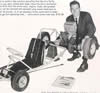
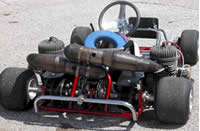
 The Center Shaft with its Friction shoes is placed onto the engine next. There should be a “keyway” cut into the inner diameter of the clutch shaft which should align with a keyway in the engine’s shaft. This keyway makes sure that the “Center Shaft” will rotate with the engine. To stop the “Center Shaft” from slipping out off the engine shaft, there is a hole to allow a “grubscrew”. A grubscrew is where a threaded small bolt will screw through the Center shaft and tighten in on the engine shaft. You may or may not receive the rectangular metal “key” with the centrifugal clutch or not. I suggest you visit a lawnmower repair shop or a hardware store to obtain a suitable “key”. Below is a photo of the Centrifugal clutch transmission complete. A plastic chain guard can also be seen. If your engine does not have a keyway, and perhaps has another PTO (power take off) Shaft Type(s) as can be seen here, then you may have to resort to welding the “Center Shaft” to the engine’s output shaft. This should only be done as a last resort.

Typical Gear Ratio and Chain Drive Setup
 On Centrifugal Clutches, the small sprocket attached to the “Bell Housing” has typically 10 teeth (although this can vary). As a rough estimate, a gear ratio of 5:1 is needed for a standard/typical go-kart/cart, with a 5hp engine running at 3500 rpm, and with rear wheels of diameter 300mm or 12inches. The speed of the go-kart can be calculated based on this “gear ratio” combined with rpm of the engine and diameter of the rear wheels (Calculate speed of go-kart). A large sprocket with 50 teeth for the rear axle can be difficult to obtain. Ask for this large sprocket at the time you are buying the centrifugal clutch and it will save a lot of looking.
Centrifugal Clutch from a Chainsaw
 Instead of buying a purpose go-kart centrifugal clutch, it is also possible to get similar centrifugal clutches in “chainsaw engines” and “mopeds/scooters”. Although these types of clutches were not designed specifically for a go-kart it is possible to adapt these to suit a different engine. As can be seen in the photo on the left, a smaller “inner bore diameter” will be found in clutches from chainsaw engines. Also, instead of a small drive sprocket attached, there will be a special star shaped sprocket, which typically drives a cutting chain. A small drive sprocket will instead have to be welded to the “Bell Housing”.
Centrifugal Clutch from a Moped/Scooter
 Inside mopeds/scooters there are also centrifugal clutches, however these are slightly different in the fact that they are “wet clutches”, where the “Bell Housing” and “Weighted Center Shaft” run in an oil bath! It might seem impossible at first that a clutch can run in oil, however the oil keeps the clutch cool and free from maintenance. Again similar to the chainsaw type centrifugal clutch, there will have to be adaptations done, as there will be a “Splined” inner bore which will need to be drilled out to suit the engine’s output shaft.
In some mopeds/scooters there are 2 centrifugal clutches each which engages at different rpm of the engine. Therefore when the scooter is going slow and the engine is slow, the first centrifugal clutch engages. This provides a high gear ratio giving extra torque at low speeds. When the moped is moving at an average speed, and the engine turns faster, the second centrifugal clutch with a lower gear ratio kicks in and changes the gear ratio. This setup is very complicated involving a ratchet type free wheel system and is not feasible for use on a kart. It is possible to adapt and use one of these clutches however on a kart.
Conclusion to Centrifugal Clutches, Chain Drive and a Single Gear Transmission for a Go-kart
Having a clutch in a kart allows for great freedom, where the engine can be started and the kart can remain stationary. It also allows the driver to stop the kart without having to turn off the engine. Depending on the weight of the kart, the speed and power of the engine, a centrifugal clutch may not be ideal, but it will work. It is the most effective and simple Single Gear Transmission for a Go-kart. It is referred to as a “Single Gear Transmission” because there is only 1 speed and 1 gear ratio that the kart can go at. As a result of there been only 1 gear ratio, there has to be a hard line drawn between fast take off speed and high end speed.
If you have any comments or queries on this article, feel free to contact the author at: kartbuilding [at] gmail.com


 There are also some excellent in-depth articles about the history of karting, right up to the current day! Some of the topics discussed include:
 The following well produced video shows the stages involved in making a Go-Kart using the


 The (1) Stub-Axle, (2) n shaped Yoke, (3) King-Pin Post make up the essential parts of the steering.
 This is the inclination of the King Pin whose top leans in a backwards direction towards the rear of the kart. This is the most important factor governing how the kart will handle. This is however, interrelated with the other angles. In the case of the King Pin inclination, the greater the angle, the greater the “jacking effect” on the chassis, and the greater the oversteer the kart will develop. If there is too little, the kart will tend to understeer. The greater the angle, the heavier the steering and tendency to self-center. In practice, many people settle for angles between 20 and 25 degrees.
 This is the inclination inwards at the top of the king pin towards the center of the kart, and it is aimed at counter-acting the jacking effect of the castor: at the same time it helps to produce a stronger joint, which will be able to withstand higher shearing forces. Generally this angle is between 10 degrees and 12 degrees, and to allow the wheels to stand flat on the floor, is offset by a similar angle on the stub axle.
 This refers to the placement of the steering arms (when viewed from above), in relation to the chassis, and the rear axle. Ideally,
  As can be seen from the following image, there are two possible arrangements of the n shaped Yoke. It can be attached to the chassis, or it can be attached to the stub axle (recommended). It is recommended that you attach the “King Pin Post” to the chassis, and that the n shaped yoke is attached to the front stub axle. This will make it easier if you are installing brakes on the front wheels. It also provides for greater clearance for the steering arm.
 If you are designing your own Kart on a
  As an example of the amount of information and the ease at which CAD software can calculate the FOS, a stress test was carried out on a Front Stub Axle from a Go-Kart, as can be seen in the image on the left. The entire