There are three different factors when deciding on the Steering Geometry for Go-Karts. Those are:
- Castor Angle
- Camber Angle
- Ackermann Angle
This article covers the above three factors in relation to Go-Karts with no suspension, and outlines typical angles and geometry which should be used. The information for this article is taken from “The NatSKA Guide to Karts and Karting” and is currently available on ebay! The off-road kart plans, and racing kart plans on this website, take into account these steering geometry angles and match the values in the above Guide.
Parts of the Steering Setup on a Kart
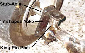
 The (1) Stub-Axle, (2) n shaped Yoke, (3) King-Pin Post make up the essential parts of the steering.
The King-Pin Post is attached/welded to the chassis.
The n shaped Yoke pivots/hinges on the King-Pin Post.
The Stub-Axle is attached to the n shaped Yoke.
These three parts are welded/attached at various angles to make steering easier on a kart. The practical side/making of these parts are not discussed here, and instead just the theoretical setup.
Castor Angle
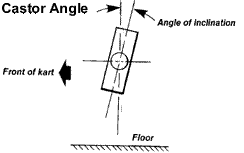
 This is the inclination of the King Pin whose top leans in a backwards direction towards the rear of the kart. This is the most important factor governing how the kart will handle. This is however, interrelated with the other angles. In the case of the King Pin inclination, the greater the angle, the greater the “jacking effect” on the chassis, and the greater the oversteer the kart will develop. If there is too little, the kart will tend to understeer. The greater the angle, the heavier the steering and tendency to self-center. In practice, many people settle for angles between 20 and 25 degrees.
Camber Angle
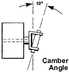
 This is the inclination inwards at the top of the king pin towards the center of the kart, and it is aimed at counter-acting the jacking effect of the castor: at the same time it helps to produce a stronger joint, which will be able to withstand higher shearing forces. Generally this angle is between 10 degrees and 12 degrees, and to allow the wheels to stand flat on the floor, is offset by a similar angle on the stub axle.
Ackermann Angle
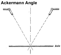
 This refers to the placement of the steering arms (when viewed from above), in relation to the chassis, and the rear axle. Ideally, lines projected through the center of the King Pins, and through the bolts holding the track rods, should meet at the center point of the rear axle. The effect of this is that the inside wheel always describes a smaller radius arc than the other wheel, when the kart is being turned – this is most especially important at low speeds, and on tight corners. The length of the steering arm, in relation to the spade/drop arm, effects the “speed” of the steering reaction. A long steering arm causes slow but very light steering, whereas a short arm causes quick steering but requires greater effort.
Correct Placement/Arrangement of n shaped Yoke
 As can be seen from the following image, there are two possible arrangements of the n shaped Yoke. It can be attached to the chassis, or it can be attached to the stub axle (recommended). It is recommended that you attach the “King Pin Post” to the chassis, and that the n shaped yoke is attached to the front stub axle. This will make it easier if you are installing brakes on the front wheels. It also provides for greater clearance for the steering arm.
The problem with installing the n shaped Yoke on the chassis, is that when attempting to achieve “full steering lock” the steering arm hits off the n shaped Yoke. This was found on a previous kart and a notch had to be removed from the steering arm to allow for extra steering lock.
Conclusion
There does be a lot of debates regarding the ideal steering setup for karts, and especially when deciding on the actual angles to use for King Pin Inclination (KPI), Camber Angles and Castor Angles. All these angles are interrelated and allow for a Go-Kart with no suspension and a solid live rear axle to steer smoothly. If you have any comments, questions or queries about this article, feel free to email me: ![]()
EDIT: There is also an excellent article cover some of the above, and also toe-in and toe-out on Racing Cars (Formula 1 etc.) http://www.ozebiz.com.au/racetech/theory/align.html
EDIT: Another excellent article with interactive Flash Diagrams http://www.bcot1.com/karting/ (local)
Hi, trying to find the setting for the front wheel axle nyloc nut.
Thanks, BS.
Hi Braz,
I’m not sure what you mean by the “setting” for the front wheel. As for how tight the nyloc nut should be, well it should not be too tight, as the front wheel needs to spin freely, and you don’t want to have the ball bearings “crunch”. You’ll have to gauge the tightness of the nut by hand.
-steve
hi steve
I have a 2005 margay chassis that I raced with but eventually took it all apart and had some cracks rewelded.when I put the front axle on I set the spacers 3 top 3 bottom on the kingpins.When I put the stering wheel on my micron on steering wheel doesnt line up on top where the wheels are straight like it did before.
Hi Chris,
You should be able to adjust the Track Rod ends ( http://kartbuilding.net/racingkart/Free_Racing_Kart_Plans_PDF/Main_Kart_Complete_11_Steering_Track_Rods.pdf ) so the steering wheel lines up. You’ll probably have to adjust both track rods to achieve this.
we race dirt carts with no suspension on a small clay over. I keep having a problem with the car be twitchy in the front end the driver says is real jerky can this be the effect of to much caster? We have played with the toe out but it does not seem to help. Any advice would be greatly appreciated.
Hi David,
Do you mean “jerky” as “over sensitive”? I.e. any movement of the steering wheel causes the kart to turn sharply?
It could be a combination of both the castor and camber angles. It could also be the fact that your steering arm is too short. (It’s set at 135mm long on this DRG: http://kartbuilding.net/racingkart/Free_Racing_Kart_Plans_PDF/Main_Kart_Complete_04_Front_Stub_Axles_and_KingPins.pdf ) Increasing the length of the steering arm should give smoother control over the steering.
It’s a case of testing and seeing. Let us know how you get on with it.
-steve
Hi the section of your article on camber is incorrect. Camber is the angle between the axle and the ground, in your example 0
Inclining the king pin is done to reduce king pin offset. Kingpin offset is the lateral distance from the centre of the contact patch to the point on the ground that the kingpin points to.
The effect of too much kingpin offset is bump steer.
The effect of insufficient kingpin offset is dead steering that lacks feel.
Hi Aaron,
Thanks for the information on Camber and King Pin Inclination (KPI). The steering setup on a kart is quite involved. There are many different angles involved. For the Camber Angle on my own kart, I went through many changes, and left it at 0 degrees for a while. On one of my karts I had rounded tyres (wheelbarrow wheels) and I found this did not work great with a large camber angle.
This webpage -> http://www.bcot1.com/karting/ goes into detail with an interactive slider explaining all the Castor, Camber, King Pin Inclination, Spindle Angle and scrub radius.
Its quite involved. If you have any examples, images etc. to compliment this, that would be a big help for people. Diagrams are one thing, but its better to see actual photos and images of the steering setup of built karts.
According to http://www.eng.uah.edu, castor angle also introduces a self-centering torque when the car is traveling forward. This is achieved by the positive offset shown in the PDF diagram. http://www.eng.uah.edu/~wallace/mae364/doc/Labs/Castor_Camber_Kingpin.pdf
my son races a small dirt trak 1/8 mi ovel kart pushes coming out of turn . may be take some cross out . curently at 57%
hi, i’m building a go kart with the n shaped yoke attached to the chassis and the king pin bolted in the n shaped yoke and free to move about the bolt. the stub axle and track rods are welded on the king pin with an angle of 104 degrees between the stub axle and track rod. their is no suspension to the kart. is it still important to consider the castor, camber and ackermann angle?